Seeing is solving
18th Nov 2022 | In News | By Mike Richardson

If you are looking to carry out reliable and efficient aircraft engine inspection, Evident Scientific provides its videoscope guide to improve the accuracy of blade tip clearance inspection. Aerospace Manufacturing reports.
During an aircraft engine inspection, measurement or quantitative analysis using a videoscope is performed to accurately determine the degree of defects. Reliable assessment using remote visual inspection enables aircraft maintenance technicians to carry out the appropriate repairs or part replacement.
Videoscopes configured for stereo measurement are widely used for aircraft engine inspections because good measurement results can be obtained when measuring objects in tight spaces, such as in high-pressure turbine (HPT) stages, commonly known as the hot section. In recent years, videoscopes with 3D modelling functions have further improved the reliability of measurements in HPTs by displaying the 3D surface shape of turbines during inspections.
A verification in the HPT that can benefit from a videoscope with stereo measurement and 3D modelling is blade tip clearance inspection. Part of the quality check of in-service turbine engines, a blade tip clearance inspection involves measuring the gaps between the engine shroud and the blade tips. A smaller gap clearance than the defined tolerance may result in damage to both the shroud and blades, while a larger gap reduces combustion efficiency and engine performance.
For high accuracy during a blade tip clearance inspection, the videoscope image acquisition and measurements need to be executed in a proper manner. To assist your blade clearance inspection, here are a few techniques for capturing images - some tips for taking accurate measurements will follow.
Tips for capturing images during blade clearance inspections:
- The first step of a blade clearance inspection is inserting the videoscope’s insertion tube into the engine’s access port. For a smoother insertion and easier navigation in the intricate and narrow spaces inside the HPT, use an insertion tube that has a scope tip with a short rigid portion.
- When approaching the scope tip to the targeted blade, make sure to get the scope tip at least 20mm from the blade. 20mm or closer is ideal. Using a stereo optical tip adapter with a wide field of view is recommended. This is so the entire object under inspection can be observed on the videoscope’s display without needing to retract the scope outside the ideal range.
- To minimise the visual difference between the left and right screens when viewing the blade, you can adjust the angle of the scope tip to place the blade edge farther away and the blade root closer. Do this by twisting the insertion tube and controlling the scope articulation. Then the 3D shape of the shroud, which sets the reference plane in the 3D modelling, can be correctly reconstructed.
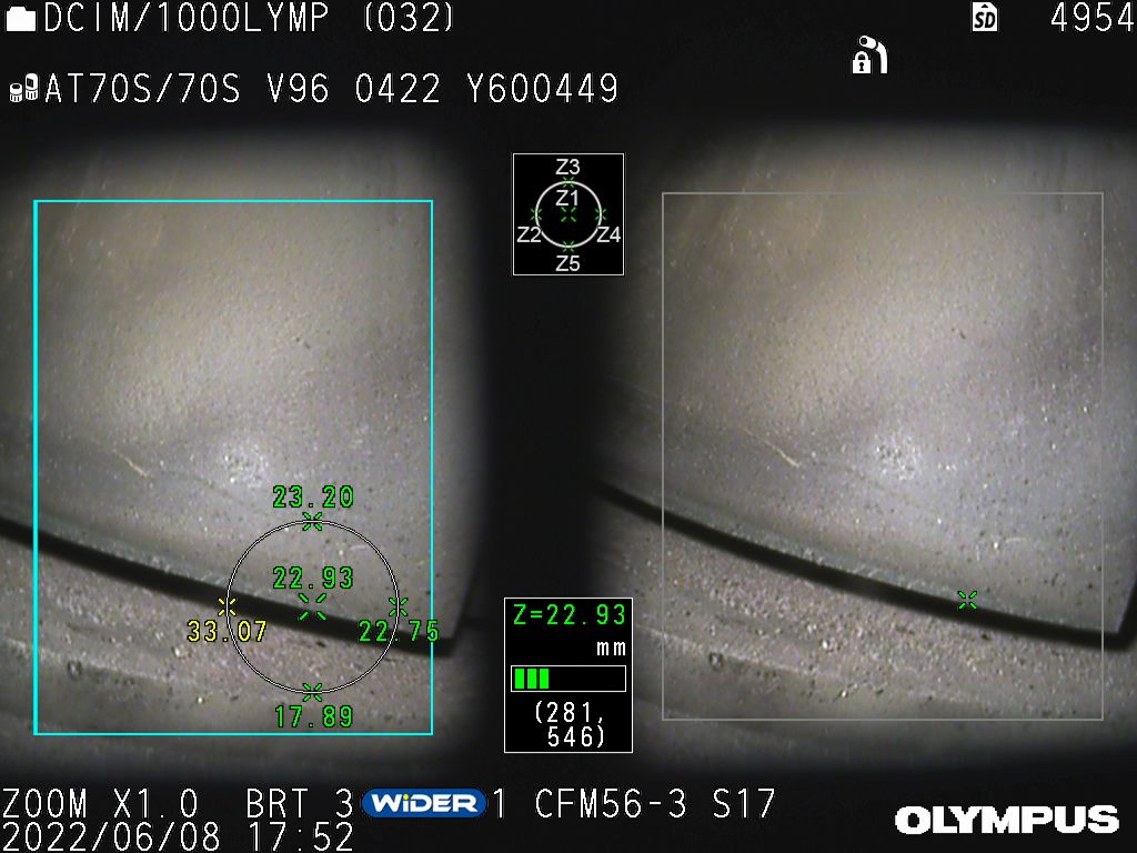
This angle adjustment technique helps to counteract the problem shown in Figure 1a on the left. When the root side of the blade is in the back and the edge side of the blade is in the front, the difference increases between the left and right shroud images. Consequently, the likelihood for incorrect measurement results is also increased.
- Using a videoscope equipped with a real-time object distance indicator eases the positioning of the scope tip. (See the circle on the image on the left side in Figure 1b.)
- Adjust the direction of the scope tip so that the shadow under the blade tip is clearly and evenly visible on the left and right screens of the stereo measurement image, and then capture the image for the blade tip clearance measurement.
Tips for taking accurate measurements:
- After acquiring your images using the proper techniques, activate the 3D modelling function to confirm that the overall 3D shape of the blade tip edge is properly created.
- Next, make sure that the root side of the blade is closer than the blade edge on the 3D image.
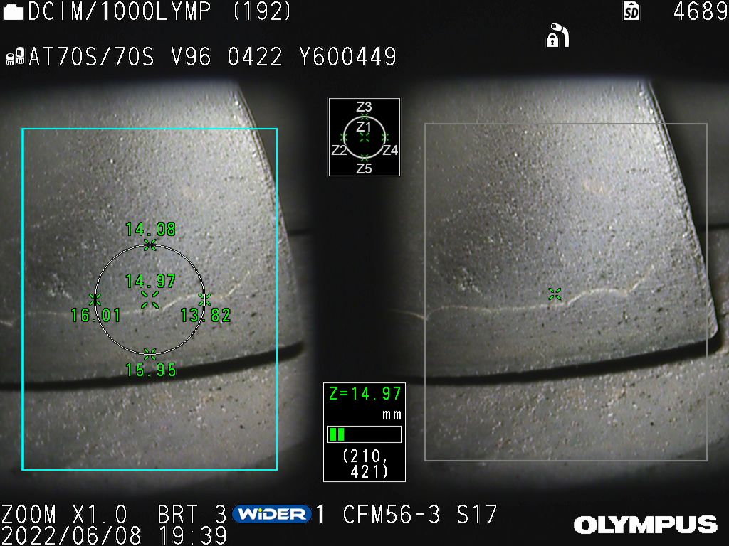
- Activating the XYZ axis display function helps you to perceive the angles of the blade and shroud images. (See each axis on the right side of Figure 2.)
- To improve the accuracy when measuring the blade clearance, zoom in on the target area before choosing your measurement points. (See the partially enlarged area on the left side of Figure 2.)
Videoscopes offering stereo measurement and 3D modelling are advantageous for taking measurements - whether for quality checks or assessing defects - in aircraft engines. They offer easy operation and high measurement accuracy. For blade tip clearance inspection, which targets uniquely shaped objects, stereo measurement improves the image acquisition reliability, and 3D modelling helps ease the execution and improves the measurement accuracy.
For reliable and efficient aircraft engine inspections, including blade tip clearance inspections, it is important to choose a videoscope capable of stereo measurement with optimised design features, such as a scope tip with a short rigid portion to ease insertion, and support functions that facilitate measurements, such as 3D modelling with zoom and a real-time object distance indicator.
Consider a free digital subscription
If you find this article informative, consider subscribing digitally to Aerospace Manufacturing for free. Keep up to date with the latest industry news in your inbox as well as being the first to receive our magazine in digital form.


