You’ve got to roll with it!
13th May 2021 | In News | By Mike Richardson

Olympus’ recently-launched RollerFORM XL scanner answers the demand for a wide-coverage and easy-to-implement phased array tool to accelerate the inspection of composite components with large surface areas. Olympus Scientific Solutions product manager, scanners & inspection solutions, Simon Alain, explains more.
In the aerospace industry, critical components such as aircraft wings are made with lightweight, durable composite material. Inspectors use non-destructive testing technology to ensure the integrity of these parts, both before they are assembled and for in-service maintenance. Ultrasonic testing is a standard method, but the parts’ extensive surface areas, the attenuative nature of composite and the complicated operation of some ultrasonic testing equipment can cause problems. Olympus’ new RollerFORM XL scanner is an innovative and easy-to-use phased array wheel probe that is all set to help resolve these issues.
Q) Firstly, please bring me up to speed with the latest news regarding new equipment.
To keep up with industry requirements, Olympus is working hard to launch solutions that bring value to our customers. Recently, we have emphasised the development of solutions for friction stir weld (FSW) inspection to address the growing use of welded metals. The automated solution includes a robot arm that precisely performs the inspection of the welds, reducing human errors. The use of ultrasonic phased array with multiple beam angles allows for the detection of randomly oriented defects, which are typical of friction stir welds.

We also recently launched the RollerFORM XL phased array wheel probe. This new inspection solution has features that allow simple yet efficient inspection of large surfaces, such as aircraft wings. Because this probe is contained in an acoustic-friendly material filled with water, it is like using a small immersion tank on the go and makes it easier to conform to curved surfaces.
Q) What types of CFRP wing testing performance demands are placed on you by today’s designers?
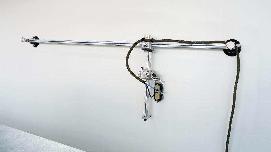
Wing inspections are particular in few ways. First, their shape includes curved sections that can be a challenge to inspect. Also, the region of interest may be on the top or on the bottom of the wing, requiring overhead inspection capability. For those reasons, it is important to develop tools that can be easily used by the inspectors regardless of shape and scanning orientation. The RollerFORM XL probe is a good example of a versatile tool that can be used in different conditions. We also recently developed a large, two-axis scanner that attaches to the surface using optional venturi-activated suction cups. This new version of the GLIDER scanner enables the inspection of large wing surfaces, even in an upside-down position.
Q) What are the most common examples of wing testing method types, i.e., NDT, ultrasound, and phased array?

Olympus’ aerospace inspection solutions include technologies such as conventional ultrasound (UT), phased array UT, bond testing, and eddy current array. These technologies can be used manually or in conjunction with encoded scanners to perform complete 2D mapping. Ultrasound techniques are used at 0 degrees or an angle beam in pulse echo mode to inspect the volume of composite materials for delaminations or metals for corrosion or other defects. While eddy current can also perform corrosion inspection of thin metal sheets, it is the preferred tool for detection of surface defects in metals or cracks around rivet holes. The bond testing technique uses a pitch-catch mode to generate a vibration on a material and listen to the vibration differences, enabling the detection of disbonds. This is particularly powerful for the inspection of honeycomb structures.
Q) Are you being forced to look at different methods as the shapes/sizes of composite test pieces become increasingly varied and complex?
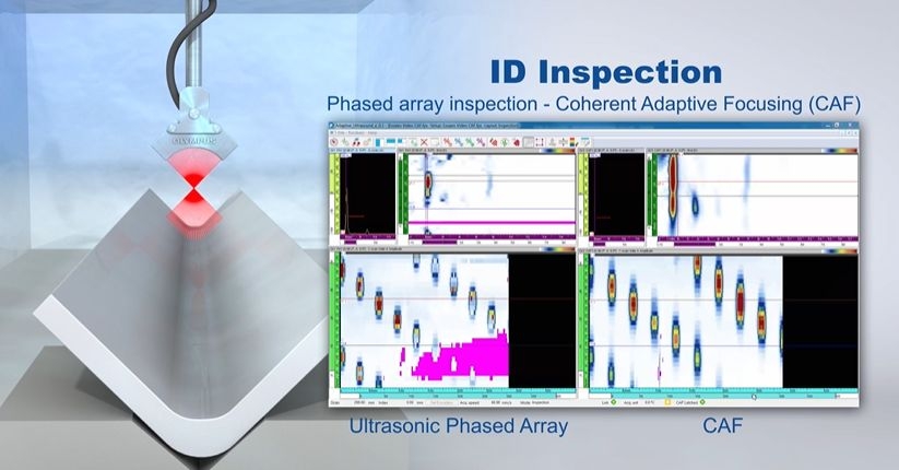
Absolutely. Positioning an ultrasonic probe according to a surface is essential to ensure reliable data. In fact, we developed the cohesive adaptive focusing (CAF) acquisition strategy to simplify the inspection of variable radiuses or opening angle components and compensate for probe misalignment by using innovative signal-processing algorithms. This method is used in immersion inspection of composite parts and adjusts the phased array ultrasonic beams depending on the relative positioning of the probe to the surface.
Q) Is the composites community looking for design parity with metals, which will mean development and acceptance of equivalent tests, both physically and in underpinning theory?
Materials modernisation is something we are always aware of and adapting to. More robust materials don’t necessarily mean more challenging inspections; sometimes it just means we need a new approach. Luckily, there are a multitude of non-destructive methods to choose from, and they all have their strengths and specialties to match the given material.
Q) In terms of your R&D, where is the main emphasis — more innovations in the hardware or the software?
We usually work on both in parallel. A solution is composed of many tools that wouldn’t be useful by themselves. It is only once they are combined that those tools enable an application to be solved. Depending on the application, those tools will either come from improvements in an existing product or the development of totally new product. Although our instruments are developed to be as flexible as possible, it is common to have to develop the probe, scanner, and software to bring the solution to a level where it will not only provide quality data but will also be easy to use and implement by the customer.
Q) How much of a role can simulation & visualisation software play in the composites testing arena?
An important feature that we brought to the market when we launched the OmniScan X3 flaw detector is the Acoustic Influence Map (AIM), an onboard simulation of the UT amplitude that’s expected in a specific region from a known defect. This software visualisation tool is used to help our customers decide if their hardware and acoustic beam combination will provide reliable data. It is very useful for an inspector to know what to expect prior to the inspection, but also to confirm that the findings (if any) make sense and are relevant. The simulation tool gives that confirmation.
Q) What composite wing-related testing developments will we be seeing in the future?
The industry is always aiming to go faster without compromising the accuracy and repeatability of the results. Ultimately, this is all about safety, so there’s no room for error. We are always working to create more tools to limit human error, make the inspector’s life easier, and help keep people safe.
Consider a free digital subscription
If you find this article informative, consider subscribing digitally to Aerospace Manufacturing for free. Keep up to date with the latest industry news in your inbox as well as being the first to receive our magazine in digital form.


