X-ray vision
26th Mar 2024 | In News | By Mike Richardson
Pascal Pinter, product manager material research and development for VGSTUDIO MAX at Hexagon examines the crucial role of computed tomography for aerospace composites.
Advances in composite development have unleashed new possibilities for aerospace manufacturing and inspired approaches to metrology and microstructure investigation that better ensure continuous product improvement and reliability. With lightweighting for performance, range, cost-effectiveness, and sustainability at the forefront, the role of computed tomography (CT) scanning and data analysis in achieving these goals is more important than ever.
Throughout its use of composites, the aerospace industry has relied on visual, acoustic, ultrasonic and, more recently, radiographic-based inspection methods, along with CMMs (coordinate measuring machines) for surface-dimension checks. Each of these non-destructive tests (NDT) plays various roles based on time, cost, product complexity, and the degree of safety required. Because many composite aerospace components push the limits of lightweighting and performance, deep interior part inspection is more important than ever for safety, risk avoidance, and business sustainability.
CT scanning and related data analysis and visualisation are ideal for today’s aerospace components. In recent years, there have been step-change advances in X-ray tomography, high-performance computing, software algorithms and user interfaces that communicate complex data that benefits CT scanning and data analysis. CT technology is unique in that it can capture full three-dimensional components including their inner structures by acquiring many detailed X-ray images over a full 360-degree rotation. That raw data is then processed by state-of-the-art software to reconstruct a dimensionally accurate 3D-volume images comprising billions of voxels (individual volume elements, analogous to 2D pixels).
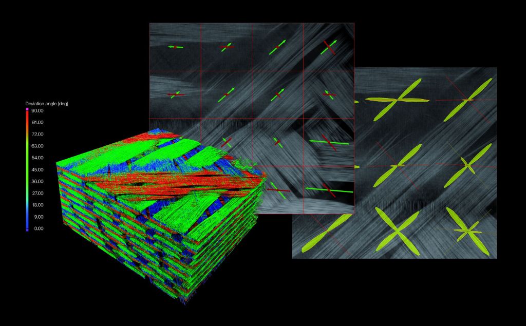
The numerical outputs and the color-coded, 3D images created by such software provide startling detail of composite microstructure, allowing for comparisons of the perfect as-designed part and as-manufactured reality. An array of specialised digital tools can analyse material density, the orientation of reinforcement structures, internal defects from design and manufacturing flaws or overload, and strain patterns calculated from scans of different states of a sample using digital volume correlation.
The comprehensive capabilities of today’s CT-scan-data analysis for commercial and experimental types of composite structures are extensive. Any structure can be captured and characterised against its design intent. Templates can be created to automatically analyse part features and problems rapidly and repeatedly. This includes porosity analysis; fibre and resin analysis for local fibre, fabric, and roving orientations; and derived statistics like orientation histograms or orientation tensors, fibre volume fractions, porosity within the resin, and more. All the data may be exported into finite element analysis tools and used for improving material modelling and structural simulations, enabling the building of comparative models for component design and R&D. In appropriate cases, these analyses are even applicable for inline inspection (ILI).
Traditional methods
The most common commercial composites fall into the polymer matrix compound (PMC) category, which includes advanced CFRP and GFRP. Ceramic matrix composites (CMC), made with long, multi-strand ceramic fibres, are also gaining recognition in high-heat applications, showing significant advantages over ‘technical ceramics’ for crack resistance, thermal behaviour, and fracture toughness.
These composite groupings, even CMC, can all benefit from the same CT-scan analysis technology for determining defect, performance, and quality-specification states. It is only a matter of having scanning machines of the appropriate size and selecting a suitable scan strategy and analysis settings. Depending on the material at hand, there are inspection solutions for each fibre architecture (short, long, and continuous), layup pattern (uni-directional or with specified angle per ply) and matrix material. Moreover, the analysis itself can be captured and automated.
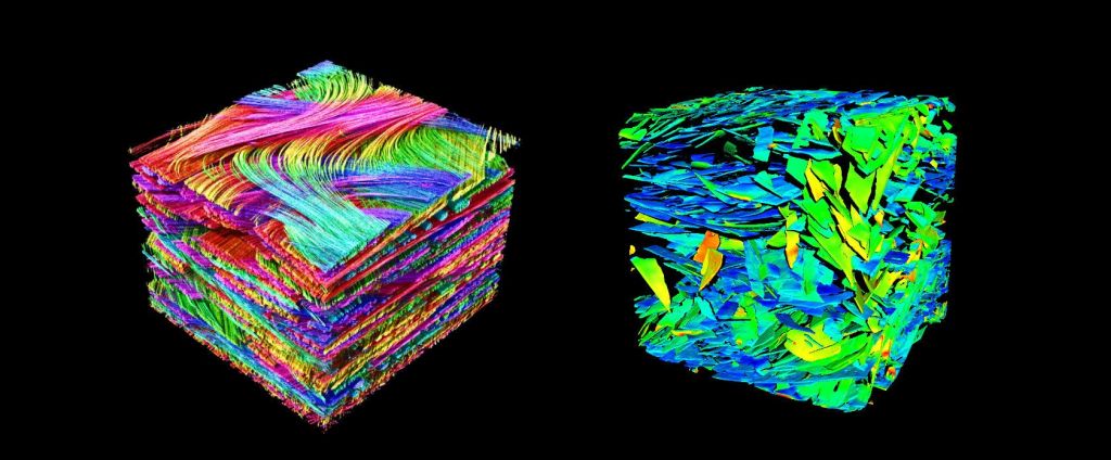
Foams are another material used in composites that can be scanned and inspected with CT-data analysis and visualisation software to better understand their behaviour. Although already in widespread use, many foaming processes are not well understood. Foams are, of course, lighter than their solid versions and can be used for low-stress applications. Good examples are physically or chemically foamed plastic in an injection moulding process.
Combined with face sheets made of the same dense material or another material that is much stiffer than the core, it is possible to create composite sandwich structures with high bending stiffness at low weight. Therefore, the pore size, material volume fraction, and the elongation of the pores are crucial in understanding the mechanical and thermal behaviour of the material.
Hybrid composite materials
Hybrid composite materials are the subject of study in both university and industrial R&D settings. While their definition can be traditional in terms of final layup structure, they can be composed of both inorganic nano/micro materials and particulates, and organic substances such as flax, hemp and cotton fibres. As new material combinations present new mechanical behaviours, it makes sense to examine their damage behaviour for R&D applications.
A technology commonly used to do this is in-situ CT testing where a material sample or an entire component is strained in a loading stage within a CT-scanner. Here, the material can be loaded and scanned simultaneously, with the resulting data used to evaluate the local displacement and strain tensor, as well as any arising cracks. However, cracks do not necessarily have to be found from in-situ datasets of material samples. It is also possible to compare CT scans of components at different states, such as before and after field tests.
There are always new composite experiments arising in research institutes where the behaviour of an internal microstructure is not well understood, either in the manufacturing process outcome or field performance. Consider, for example, the gas-pressure infiltration of metallic glass with aluminium. The production of this material via this process is still new, requiring scientists to gain more information about reinforcement distribution and orientation. Advanced CT-scan analysis can offer deep insight into these challenges by providing data at the prototype and post-test stages.
CT analysis in action
Manufacturing costs for composite materials are gradually declining, while production efficiency is increasing. CT offers a means for similarly improving quality assurance across a wide range of industries.
There is no industry more safety-bound than aerospace, which often employs fibre composite material analysis (FCMA) to ensure quality and certification. Many of its applications use unidirectional (UD)-reinforced materials when the loading direction is a certainty. A good example is helicopter rotor blades. Detection of deviation between desired and actual fibre orientation in these blades is critical because the fibre can only support loads in one direction.
Helicopter blade production is largely characterised by manual work performed by highly trained personnel. Every component of such a safety-critical product is checked against specifications for defects such as pores, delaminations, or waviness in fibre deposition. As mentioned, blade stresses are best carried in the longitudinal direction of the fibres. This is where the detailed orientation analysis provided by advanced software comes into play.
CT-based analysis can expose deviations in fibre orientation, which can vary blade by blade, allowing results to be easily reviewed by engineers. Until industrial CT came along, the only way to inspect rotor blades was to destroy them. This process laid waste to numerous samples, making it a far too costly practice.
Much of the CT scanning and data analysis for composite products is still confined to the R&D stage, where lab work is studied and then tested against manufacturing outcomes. A great deal of knowledge is captured here that, with final field-collaboration testing, can lead to safe assumptions about the behaviour of many types of parts in digital engineering processes using multi-scale material models to calculate accurate allowances, and help mechanical engineers account for non-linearity and anisotropy in structural analyses.
However, this abbreviated practice does not take into consideration the potential total-cost savings of a more rigorous approach to inspection, as other manufacturing processes could benefit from advanced inspection technology, including microscopy and coordinate-measuring technologies.
Application of CT analysis during production is on the rise, from mainstream materials such as metals to the most multi-faceted composites. It is becoming imperative for all mission-critical composite parts to get as close to inline series inspection as possible. Automation of both software analysis and production inspection are making advanced CT scanning and data review more and more feasible for competitive, high-performance composite-part manufacturers.
Consider a free digital subscription
If you find this article informative, consider subscribing digitally to Aerospace Manufacturing for free. Keep up to date with the latest industry news in your inbox as well as being the first to receive our magazine in digital form.


